
")
Identification and development of tech specs and concepts
If our customer cannot and only partially can define its technical specifications, the first step is to identify the required parameters of the circuit together.
After defining the customer’s requirements and specifications we prepare a system design that shows all the subfunctions, interfaces, connections of the circuit or device under design. This system plan allows us to make a cost calculation of the project and to identify the human and technical resources needed.
Schematic design
Based on the results of system design a circuit diagram is designed. In this stage we identify and select components, connectors, circuit sections that may be suitable and necessary for the device. Datasheet diving and literature interpretation is carried out to make sure all of above fit the needs.
Depending on the type of the circuit, but especially in case of analog and power electronics circuits, simulations are performed to verify operation and paper calculations. We use Analog Devices’ LTSpice or Texas Instruments’ PSpice for TI software. In case the customer’s request only applies to the schematics design then the development is done in this step handing over all the generated documents to the customer.
Layout design
Depending on the mechanical requirements and the complexity of the circuit, a double or multilayer PCB is designed. During the component layout and the routing, we proceed according to the specifics of the circuit. Whether high-voltage, low- or high-current, high-speed differential layout technique is needed we carry out it in harmony with the professional principles.
We also apply the principles of manufacturability and testability during the design of the circuit diagram and the printed circuit board. The latter means not only the placement of test points, but also the design of test specific circuit parts and interfaces, which is not only essential but speeds up functional testing. By generating a three-dimensional model, we can help with mechanical design.
Prototyping and firmware programming
If the customer needs, then we will assemble the prototype of the designed circuit to test its operation. When developing firmware, it is absolutely necessary to build a prototype. The prototype will be handed to the customer for operational verification tests and design approval.
Depending on the type of the circuit, a variety of manual tests are required to verify that the circuit is operating to specifications in all manners. Testing of the prototype circuit includes, among other things, measuring the noise of the power rails, checking the current consumption of the supply rails, checking the operating time in the case of a battery-powered circuit, and oscilloscopic analysis of the current consumption characteristics. If the developed device has firmware also, its programming is done as one of the steps of prototyping.
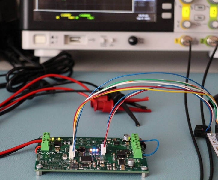
Thanks to our radio frequency measurement equipment, we can perform EMC pre-compliance tests in-house. This means the emission measurement of conducted and radiated radiofrequency signals and the verification of the immunity against conducted and radiated RF signals in accordance with the parameters described in the relevant standards for the device.l.
Depending on the results obtained from the above measurements, development may continue by redesigning parts of the circuit.
Production-ready documentation
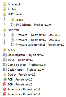
As the final step of the development all the generated documents are made available for the customer, including:
- Schematic and layout in CAD and PDF format,
- BOM with pick&place files optionally,
- Embedded firmware and/or PC software
- Measurement results, calculations, simulations.
We take care of our project in their later lifetime: we offer repair and calibration services for them.
As described above, we are happy to deal with:
- Local or remote embedded DAQ and control devices, including the sensor signal conditioning to the graphical interface,
- Application specific power supplies, LED or laser diode driver circuits,
- Internet or network based DAQ devices and systems,
- Renovation or retrofitting instruments, electronic devices
- Precision references; fixed or variable, current or voltage sources,
- Scientific/research related specialties; power supplies, high or extra low voltage, low noise, high current supplies.
We also undertake integration or development of measurements systems for electrical or non-electrical parameters, such as:
- Extra low-range resistance measurement device,
- Surface or volume resistance measurement system for insulator materials.
Contact us
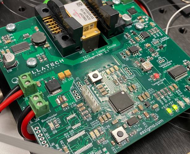
Impulzusüzemű lézerdióda-meghajtó áramkör TEC meghajtóval.
Az áramkör maximum 9 amperes árammal és 2 MHz-es frekvenciával képes meghajtani a kimenetét.
![]()